Friday, 10 December 2010

Schlieren Photography: 10.12.10


Schlieren photography is a visual process that is used to photograph the flow of fluids of varying density. Invented by the German physicist August Toepler in 1864 to study supersonic motion, it is widely used in aeronautical engineering to photograph the flow of air around objects. Its role is changing due to the increasing use of computational fluid dynamics, where the same principle is used to display the computed results as flow images.

http://en.wikipedia.org/wiki/Schlieren_photography

Shadowgraph: 10.12.10


Shadowgraph is an optical method that reveals non-uniformities in transparent media like air, water, or glass. It is related to, but simpler than, the schlieren and schlieren photography methods that perform a similar function. Shadowgraph is a type of flow visualisation.
In principle, we cannot directly see a difference in temperature, a different gas, or a shock wave in the transparent air. However, all these disturbances refract light rays, so they can cast shadows. The plume of hot air rising from a fire, for example, can be seen by way of its shadow cast upon a nearby surface by the uniform sunlight.

http://en.wikipedia.org/wiki/Shadowgraph

More Schlieren: 10.12.10

Schlieren photography is a visual process that is used to photograph the flow of fluids of varying density

There are several methods commonly used to visualize refractive index or density changes in liquids, gases, liquids and solids.

Generically these include shadowgraphs, schlieren and interferometric techniques. These sytems are used to visualize temperature gradients, shock waves in wind tunnels, nonhomogeneous areas in sheet glass, convection patterns in liquids, etc.

The focusing schlieren method:


http://people.rit.edu/andpph/text-schlieren-focus.html

Structure for the mirror: 10.12.10

Desert Effect: 10.12.10


A mirage is a naturally occurring optical phenomenon in which light rays are bent to produce a displaced image of distant objects or the sky. The word comes to English via the French mirage, from the Latin mirare, meaning "to look at, to wonder at". This is the same root as for "mirror" and "to admire". Also, it has its roots in the Arabic mirage.
In contrast to a hallucination, a mirage is a real optical phenomenon which can be captured on camera, since light rays actually are refracted to form the false image at the observer's location. What the image appears to represent, however, is determined by the interpretive faculties of the human mind. For example, inferior images on land are very easily mistaken for the reflections from a small body of water.

Camera Obscura: 10.12.10

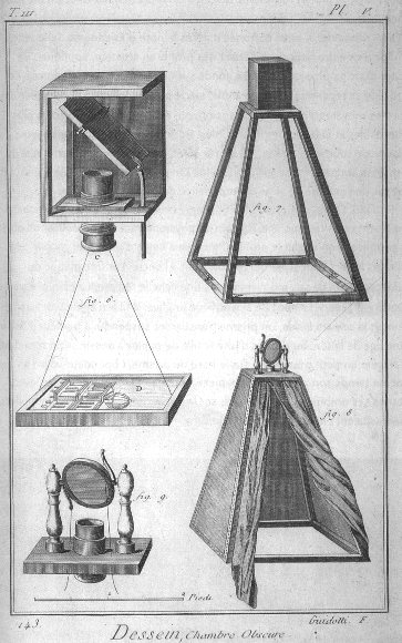
The camera obscura (Latin; "camera" is a "vaulted chamber/room" + "obscura" means "dark"= "darkened chamber/room") is an optical device that projects an image of its surroundings on a screen. It is used in drawing and for entertainment, and was one of the inventions that led to photography. The device consists of a box or room with a hole in one side. Light from an external scene passes through the hole and strikes a surface inside where it is reproduced, upside-down, but with colour and perspective preserved. The image can be projected onto paper, and can then be traced to produce a highly accurate representation.
Using mirrors, as in the 18th century overhead version (illustrated in the Discovery and Origins section below), it is possible to project a right-side-up image. Another more portable type is a box with an angled mirror projecting onto tracing paper placed on the glass top, the image being upright as viewed from the back.
As a pinhole is made smaller, the image gets sharper, but the projected image becomes dimmer. With too small a pinhole the sharpness again becomes worse due to diffraction. Some practical camera obscuras use a lens rather than a pinhole because it allows a larger aperture, giving a usable brightness while maintaining focus.


http://en.wikipedia.org/wiki/Camera_obscura

Torch: 09.12.10


The torch has been ordered via the internet by Immo

Lumapower Mentor MT-E Torch with 500 Lumens and one central LED Bulb

http://www.torchdirect.co.uk/lumapower-torches/lumapower-mentor-mt-e-torch.html

Thursday, 9 December 2010

Parabolic Mirror: 09.12.10


http://www.greenpowerscience.com/PARABOLICSHOP/25PARABOLICSALE.html

SIZE-----------------25"H X25"W
* POWER EST.-----------8.0
* BEAM-----------------SPOT
* BEAM SIZE MAX POWER--1 INCH (additional scatter"4)adds background heat
* FOCAL LENGTH---------21 INCHES FROM OUTER RIM - 23 INCHES FROM CENTER BASE
* WEIGHT --------------3 LBS.
* MAX TEMP. CLIMB------1251 F IR THERMOMETER
* MAX COLLECTION-------1607F
* MATERIALS TESTED
* WATER------------12oz. BOILS 120 sec.
* WOOD-------------FLAME .2 SEC.

Research: 09.12.10

LED Laser Torch
Parabolic mirror focal length
Camera obscura
Further schlieren photography techniques
- Why the razor blade
Installation layout
Structure for the mirror
Dessert effect

Class Meeting: 08.12.10

We experimented until we had utilised all of the new equipment we had brought in and still we need to do further reaserch and buy more equipment, including an LED laser torch, a structure to house the mirror and to find out the focal length of the mirror from the supplier.


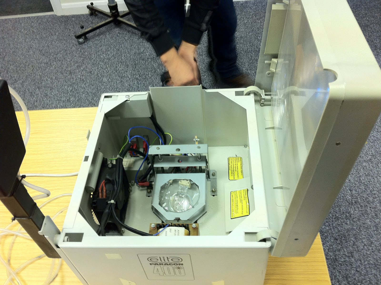
Whilst experimenting down in our newly assigned room in the basement in the TC building Ray came across an old photography enlarger that we might be able to utilise in our installation in a way of a structure to house all of the components.


The images above are some of which we took on Wednesday during our experiments. The images show the light source reflection from the mirror onto a piece of white card. Although theses images don't show the results we saw with our eyes, we did actually see some sort of results. Whether they were Schilren effect or not we still have more experiments to action. We saw what looked like a dessert effect, heat patterns / waves come out from the lighter and also the soldering iron.

Sunday, 5 December 2010

Assignment Two Thoughts: 05.12.10

Presentation: part one:

A 'hands on' demonstration of your virtual world

Presentation Part two:

justify the context and design

Submission:

Justification - max 500 words

Supporting Studies:

Concept/Idea/Realisation/Design (visualisations/sketches/images)
- Concept
- 3D Visualisations of exhibition istallation

Contextualise with an audience in mind (Kinetika)
- Contextualise

Technical research/tests requirements (pictures/films etc!)
- Technical requirements for exhibit

Time scopes/costs/Health & Safety/project management

Experiments

Research / References / Artist relations

Blog / Diary:
- Blog

Exhibition / Installation Documentation:
- Images from exhibition
- Feedback from exhibition
- Critical analyse of Exhibition and art work

All into a bound document

Sallys Thoughts: 05.12.10

- 'Flow visualisation' is really what we are trying to accomplish with our work and Schlieren is only 'one' (& presently our chosen) method that can be used to visualise this.

- for me it is the realisation of these hidden attributes of nature and natural phenomena that exist all around us, and the 'unseen' physics and mathematical wonders of nature that I find very interesting (truly amazing really!!)

- the unpredictable!! (or are they? many patterns in nature may exist as a result of calculable known formulae and principals of physics)

- patterns created in swirling smoke or the way air and water create unseen furls and vortex's in the route it takes as it 'migrates' or 'infuses' with another substance, or progresses on it's natural and eternal journey, or just in the movement of a breath, or a gentle motion or gesture, that although it is taken for granted by all of us

- it is this hidden complexity in an apparent simplicity or 'nothingness' (i.e air, water, atmosphere etc.),

- which is how 'all' life is supported and sustained. Our existence throughout time is based on the ability of the constant interchange of substance and matter

- as the intricate and complex process of the oxygenation of our blood which is then distributed throughout our bodies via our heart, to our vital organs which occurs without us even being conscious of it.

All of this is so much more incredible than is realised.

These apparently simple, yet incomprehensibly complex occurrences are potentially breathtakingly beautiful and I hope that we can capture and convey the immense hidden importance that belies the enigma of the forces of life itself.

Please do not lose sight of this as to me it is the essence of our work.

- this link from the has some amazing and inspiring flow visualisation images.

- Perhaphs we should consider the use of stills and/or film in conjunction with our installation as a medium to convey our message.

http://www.colorado.edu/MCEN/flowvis/index.html

By the way - the film on Youtube is very good but please also look at the 'Galleries' tab for a wider range of stills and footage.

Assignment Two: 05.12.10

Type: Justification and demonstration of virtual reality artifact.
Weighting: 70%
Timing: 15 mins

1. Modelling files used in *.m? format - where appropriate

2. Unity/Flash/Quartz Composer/ Other composition file

3. Hard copy of justification - max 500 words.

Assignment One Feed Back: 05.12.10

Group feeback:
The group presentation was rather well structured and organised as a whole, however there was so significant overlap and redundant sections between the individual contributions.
Despite the relatively clear technical background, it was felt that the proposed project lacked some artistic depth. The proposed meaning and aim of the work wasn't clear at all, and there seemed to be some confusion over the (working) title.
Individual feedback:
The presentation consisted in a poorly structured and uncontextualised list of references in the form of art works or practitioners. Although each of them was rather clearly presented, seemed relevant and related to a common theme, the connections between them were not made obvious and there was no real critical analysis and identification of a specific research stream.
The paper is not structured beyond the list of reference material, mirroring the subject matter of the presentation.
The technical diagrams of the proposed installation often don't communicate properly: they need simplification and better labelling. They should conform more closely to agreed conventions of technical drawing.
Presentation remarks: No student number is present on the paper that has been submitted. The paper isn't bound.

Mark: 50

Tutors: Olivier Ruellet & Andrew Moller

Comments on Feedback:

I do feel this is a far overall mark as the time we have had to develop this idea has been lacking. The group has taken longer than expected to come together and decide on a final idea which is still decidedly ropey! Hopefully over the next month this 'idea' will flourish into a justifiable piece of artwork ideal for Kinetica.

LED Laser Research: 05.12.10

Ideally our light source would need something that has an LED with a laser like quality as one bulb, that can be plugged into a power supply preferable the mains.


210 Lumen Aluminium Torch £49.99, This maybe the perfect starting point for our experiments as its not to powerful but should give greater results than with the V9 Micro laser pen and its a little cheaper.

http://www.maplin.co.uk/Module.aspx?ModuleNo=503167


750 Lumen CREE Torch £69.99, This looks like it will be really powerful with 750 Lumen, maybe too powerful!

http://www.maplin.co.uk/Module.aspx?ModuleNo=503166


LED Lenser V9 Micro Laser Torch £9.99, This is what we have used for our earlier experiments. The results were there but not bright enough.

http://www.maplin.co.uk/Module.aspx?ModuleNo=97720

Saturday, 4 December 2010

Group Meeting: 04.12.10


We met up today in order to get some much needed experiments in, We met at 10am at the St Mary's building of TVU in our newly appointed room in the basement.
We all brought along various equipment in the hope that we would get better results that our last experiments. Hadjar had also placed an order for a parabolic mirror from the states that we saw for the first time.

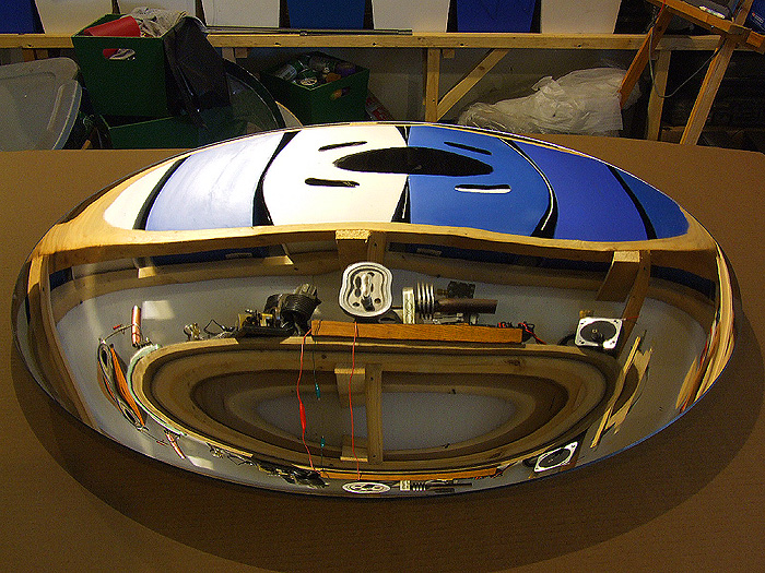
The mirror was not a mirror it turned out see had ordered a plastic concave mirror with a reflective surface, i'm not so sure our results will now be as good as we would like them to have been with a real piece of glass with a focal length.

We continued on with our experiments by taking apart the overhead projector and repositioning the parts where they were better suited for our experiment.

We set up the equipment according to the Schilren photography technique and set out to try and get some sort of results.

We fiddled with the overhead projector, blocked the light into cone shapes and also tried to narrow the be
an by covering the bulb with foil and poked a very small hole it to allow the light to shine through.

We moved the angle of the mirror around which we had clamped in place using a work clamp and photography clamps, This achieved a better angle for the light to be shone into.

The reflection back from the mirror we caught on a piece of white card as the strength of the light source we used was not strong enough to give us a large clear refection.

We managed again to see the effects of this technique, but it was small and not that clear, but an improvement on the last experiment.

We changed the light source back to using the LED pocket laser torch and are results were better than with the overhead projector.

We have decided to call it for the day as we had exhausted our resources and need to research further on the possibilities of using a more powerful LED Laser torch.

We did have one thought about using a torch, how would we power it? as replacing the batteries would not be cost effective.

We will be meeting again on Wednesday the 8th of December to experiment further, hopefully with a greater powered light source.

Wednesday, 24 November 2010

MA Meeting: 24.12.10


During our MA session we experimented with an overhead projector to see the capabilities of using it as the light source for our installation. We came to the conclusion that we would at our meeting on the saturday ahead remove and reposition some of the parts in order for us to use it in our experiments.

Concave Mirror: 24.11.10

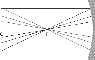
A concave mirror, or converging mirror, has a reflecting surface that bulges inward (away from the incident light). Concave mirrors reflect light inward to one focal point, therefore they are used to focus light. Unlike convex mirrors, concave mirrors show different image types depending on the distance between the object and the mirror.
These mirrors are called "converging" because they tend to collect light that falls on them, refocusing parallel incoming rays toward a focus. This is because the light is reflected at different angles, since the normal to the surface differs with each spot on the mirror.


href="http://www.splung.com/content/sid/4/page/concavemirrors">http://www.splung.com/content/sid/4/page/concavemirrors

http://en.wikipedia.org/wiki/Concave_mirror#Concave_mirrors